37+ position control system block diagram
Finding the transfer function of overal system after PID control As mentioned earlier the overall model. This control system enhances the robustness of the system.

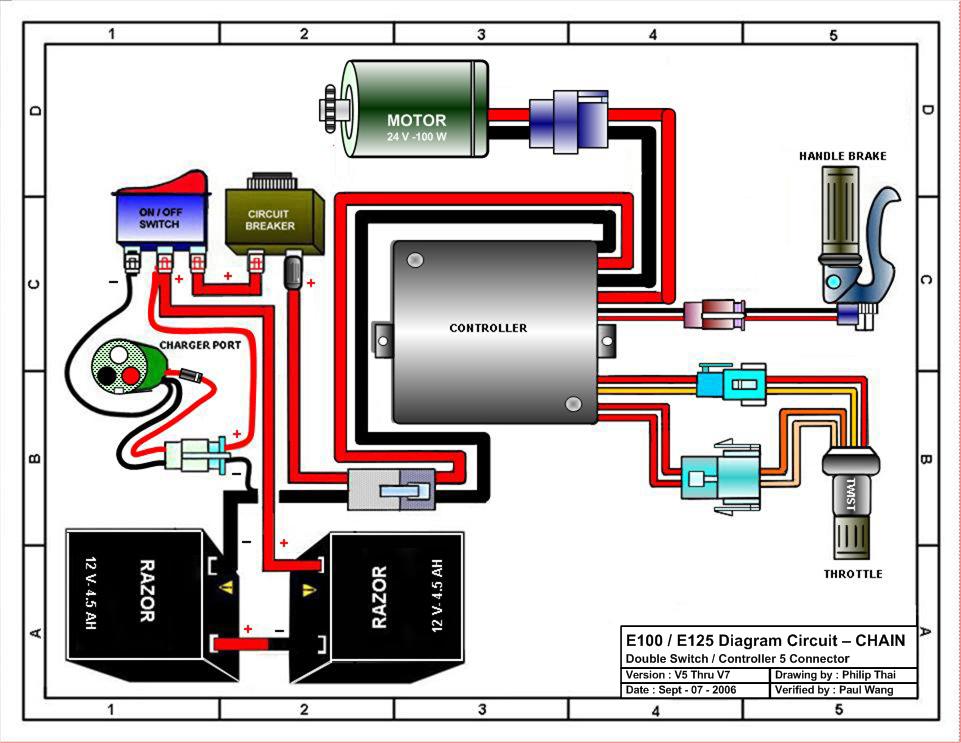
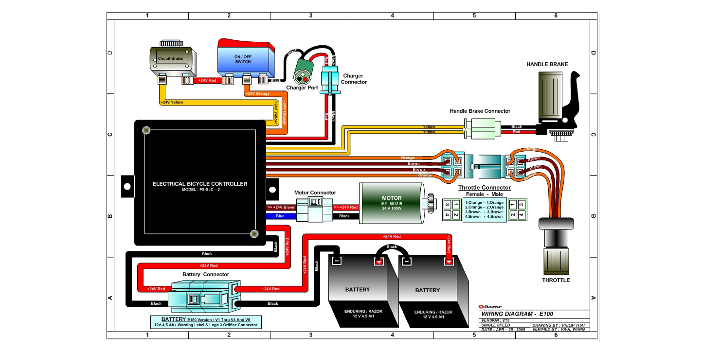
Razor E125 Electric Scooter Parts Electricscooterparts Com
In general however it Sign in to download full-size image Figure.

. This plant contains a position control system and a proportional controller to be de- signed by the user. Any system can be described by a set of differential equations or it can be represented by the schematic diagram that contains all the components and their. When we want to apply a different input signal to the same block then the resultant input signal is the summation of all the inputsThe summation of an input signal is.
A control system based on the principle of forced dynamics control for an electric drive with a permanent magnet synchronous motor and a flexible coupling is. 7 8 Figure 6. Apply block diagrams to describe the functions of control systems Figure 431-2.
It produces reliable and repeatable performance. Block diagrams Each block is completely independent of the block before and after it we assume there is NO LOADING Solve for the highest order term and then add blocks and summing. All systems take some input or inputs perform some process in the plant to.
A block diagram representation in which there is only one forward and feedback block along with a single summing point and take-off point is the simplest form of closed-loop control system. Its operation varies with each set of application parameters. 6 controller transfer function is Gcs so.
Write down the differential equations representing the system. A simplified block diagram of this plant is shown in Fig. The steps to be followed to draw a block diagram of a system are given below.
The input shaft angle and the. This system also reduces the disturbance compared to the open. Find Laplace transform of these.
Block Diagram in control systems. A basic governing system block diagram is shown in Figure 3-37.

Generalized Input Output Configuration Of Measuring Systems 40 Pages Answer In Google Sheet 1 9mb Latest Update Kevin Study For Exams

Servo Motor Types And Working Principle Motor Electronics Circuit Buffer Amplifier

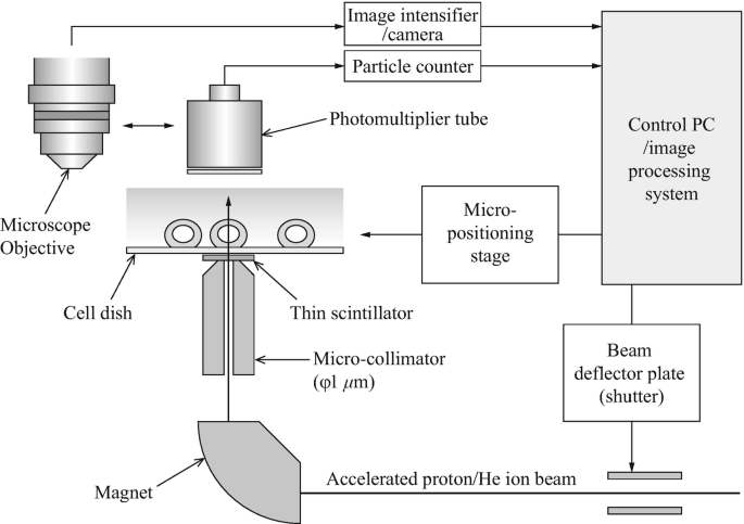
Experiments Of Local Irradiation Of Cells With Heavy Ion Microbeams Springerlink
2

Servo Motor Types And Working Principle Motor Automation Electronics Circuit

Fast Silicon Carbide Mosfet Based High Voltage Push Pull Switch For Charge State Separation Of Highly Charged Ions With A Bradbury Nielsen Gate Review Of Scientific Instruments Vol 93 No 9

Pin By Etechnog Group On Electronics Block Diagram Stepper Motor Circuit Diagram

Razor E125 Electric Scooter Parts Electricscooterparts Com

I Have A 1997 Ford Explorer And I Only Get Vacuum To The Heater Switching Valve When The Dashboard Setting Is On Off
2

Block Diagram Of Engine Control Unit Engine Control Unit Block Diagram Electrical Circuit Diagram
2

Electronic Control Unit In Automotive Electronics Electronic Control Unit Ecu Is Age Electronic Control Unit Engine Control Unit Crankshaft Position Sensor
2
2
2

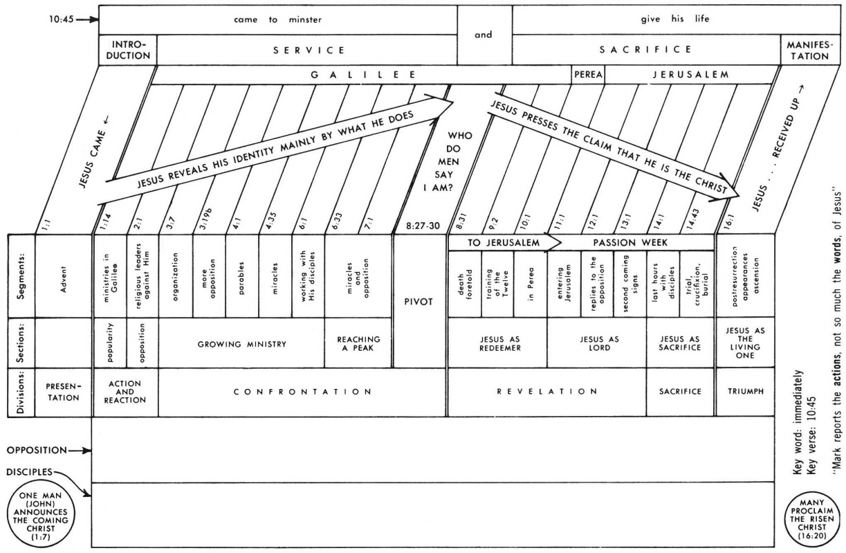
Mark 14 Commentary Precept Austin